Functional Overview
This is a replica of the NeXT SoundBox on a scale of 1:2 with a custom USB-Audio controller board, which drives a mono speaker. The circuit converts digital audio data from the USB port into an analog signal, amplifies it, and outputs it to a speaker. The following diagram shows the path from data to sound.
Component Blocks in Detail
The circuit is divided into four main functional groups.
USB Input
This part of the circuit is the interface to the outside world. It receives power and data from the USB port, filters the voltage, and protects the entire circuit from electrostatic discharge.
USB1: USB Type-B Jack
Physical interface to the host. Provides +5V (VBUS), Ground (GND), and the differential data lines D+ and D-.
L1: Ferrite Bead
Filters high-frequency noise from the USB power supply before it reaches the circuit.
U1: USBLC6-2P6 (ESD Protection)
Protects the sensitive data lines (D+, D-) and the VBUS line from damage caused by electrostatic discharge.
LED1 & R1: Power Indicator
A green LED connected directly to the 5V line to indicate that the USB port is supplying power.
USB DAC (PCM2706)
This is the digital core of the sound card. This functional group receives the digital audio stream from the USB connection and converts it into an analog stereo sound signal.
U5: PCM2706
The heart of the circuit. This chip is a stereo audio DAC with an integrated 3.3V LDO. It is powered by the 5V VBUS and generates its own internal supply voltages.
X2, C30, C31, R13: Oscillator Circuit
A 12MHz crystal with appropriate circuitry generates the precise clock signal required by the PCM2706 for USB communication and audio synchronization.
C24, C26, C27, C28, C29: Decoupling Capacitors
These capacitors are placed directly at the power supply pins of the DAC to stabilize the internally generated voltage and filter high-frequency noise, which is crucial for good audio quality.
Stereo to Mono
This simple passive circuit combines the left and right audio channels from the DAC into a single mono signal and prepares it for the mono amplifier.
R3, R4, C4: Passive Mixer
Resistors R3 and R4 (10kΩ each) mix the left and right channels from the DAC into a single mono signal. Capacitor C4 couples this signal to the amplifier and filters out any DC component.
Mono Amplifier (PAM8302A)
The final stage in the signal chain. This module takes the weak mono audio signal and amplifies it with enough power to drive a speaker.
U3: PAM8302A
An efficient Class-D mono audio amplifier. It takes the weak mono signal at the input (Pin 4) and amplifies it to drive a speaker.
C3: Input Coupling Capacitor
This capacitor at the amplifier input allows the audio signal to pass through while blocking any DC components.
R8: Pull-down Resistor
Prevents "popping" noises during power-up and power-down by keeping the input at a defined level.
H1: Speaker Terminal
A 2-pin screw terminal for connecting the speaker.
C32: Bulk Capacitor
This large capacitor stabilizes the 5V supply for the amplifier, providing extra current for loud bass notes.
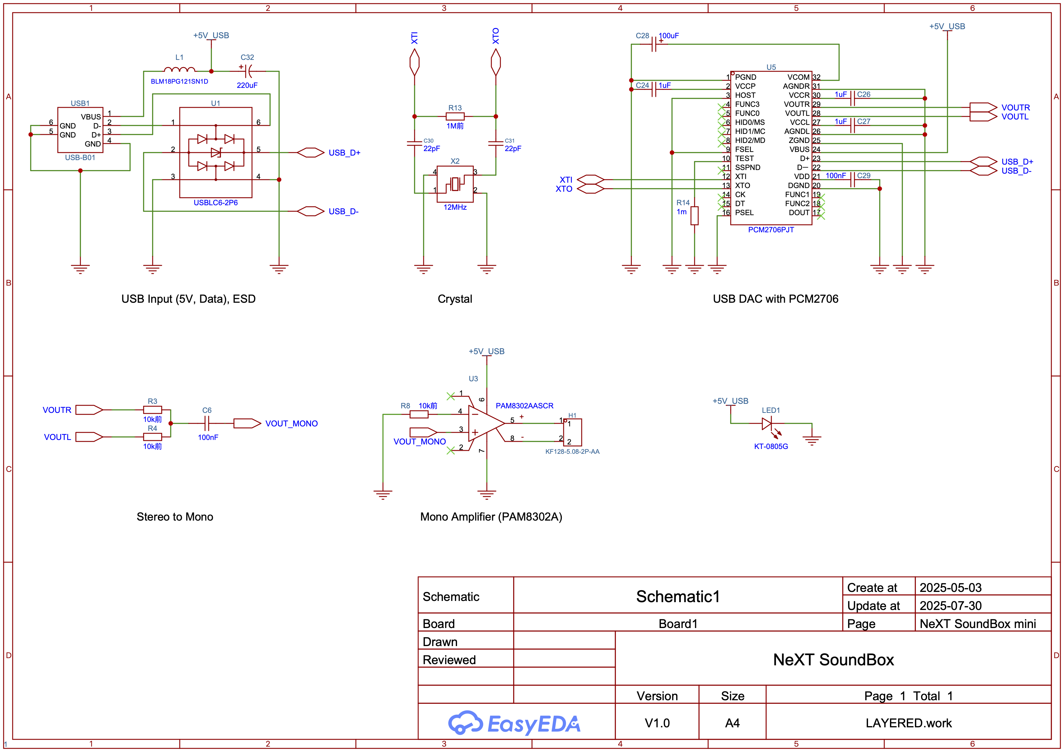
Full Schematic
Interactive Bill of Materials
The following table lists all components required for this circuit. You can sort the table by clicking on the column headers.
| Reference ▾ | Value/Designation ▾ | Package ▾ | Description | LCSC Part # |
|---|